We passed inspection! Commissioning is set for 9/13.

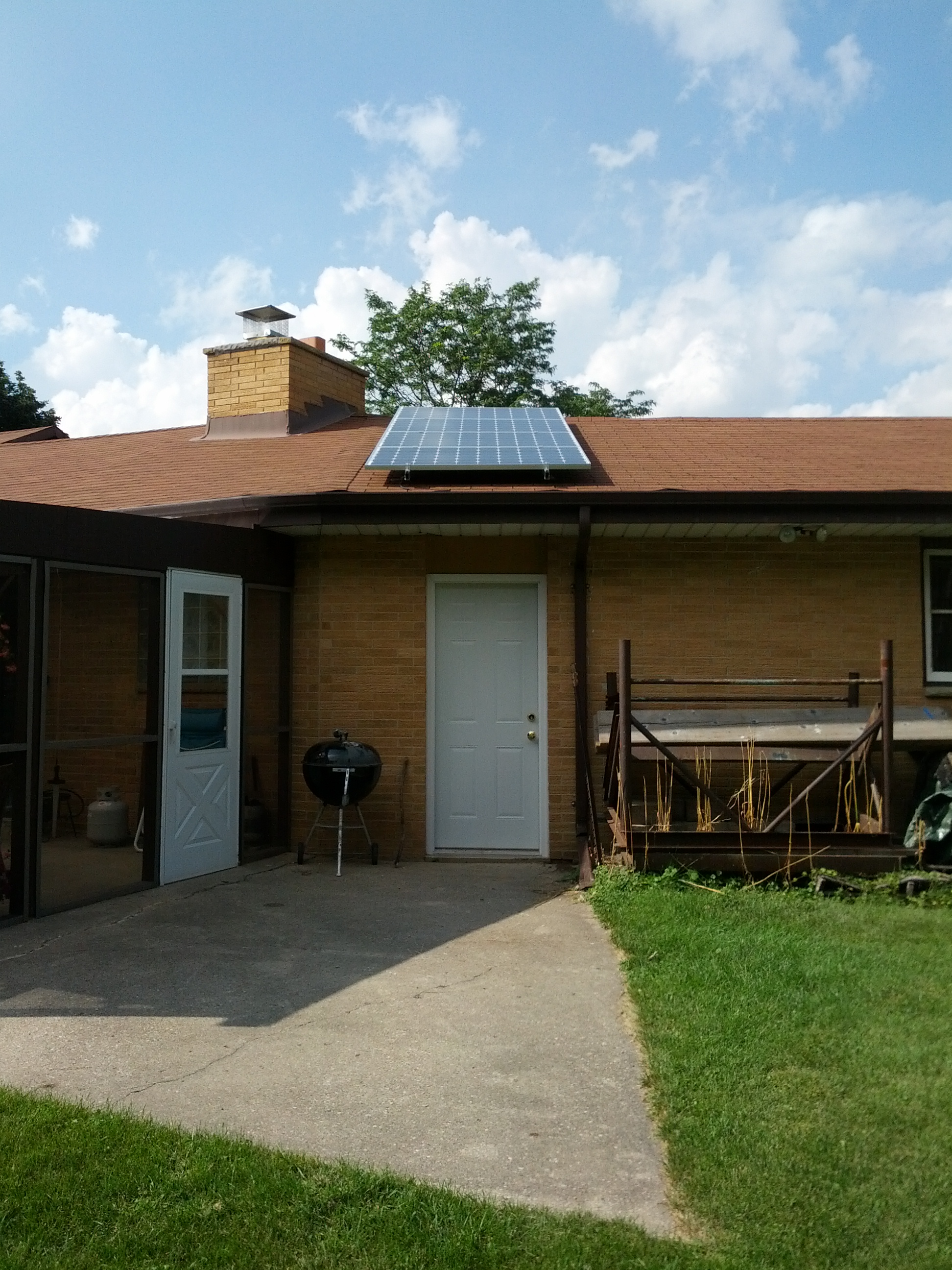
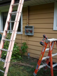
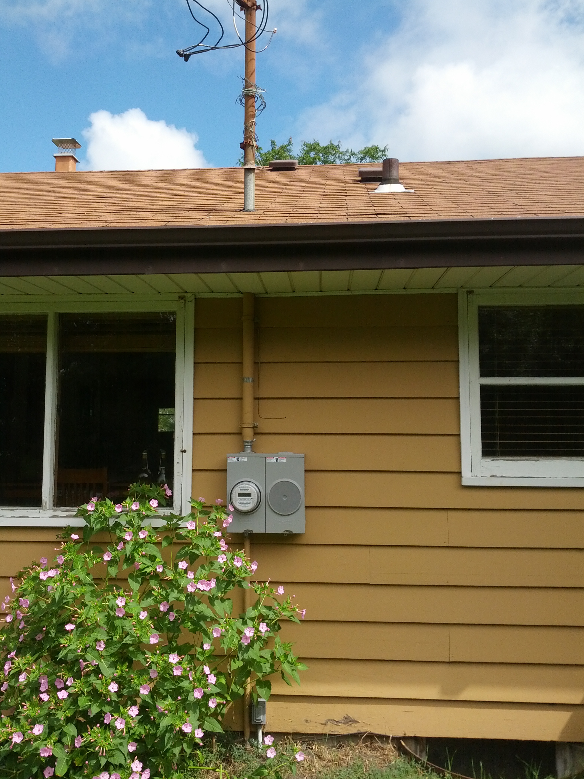
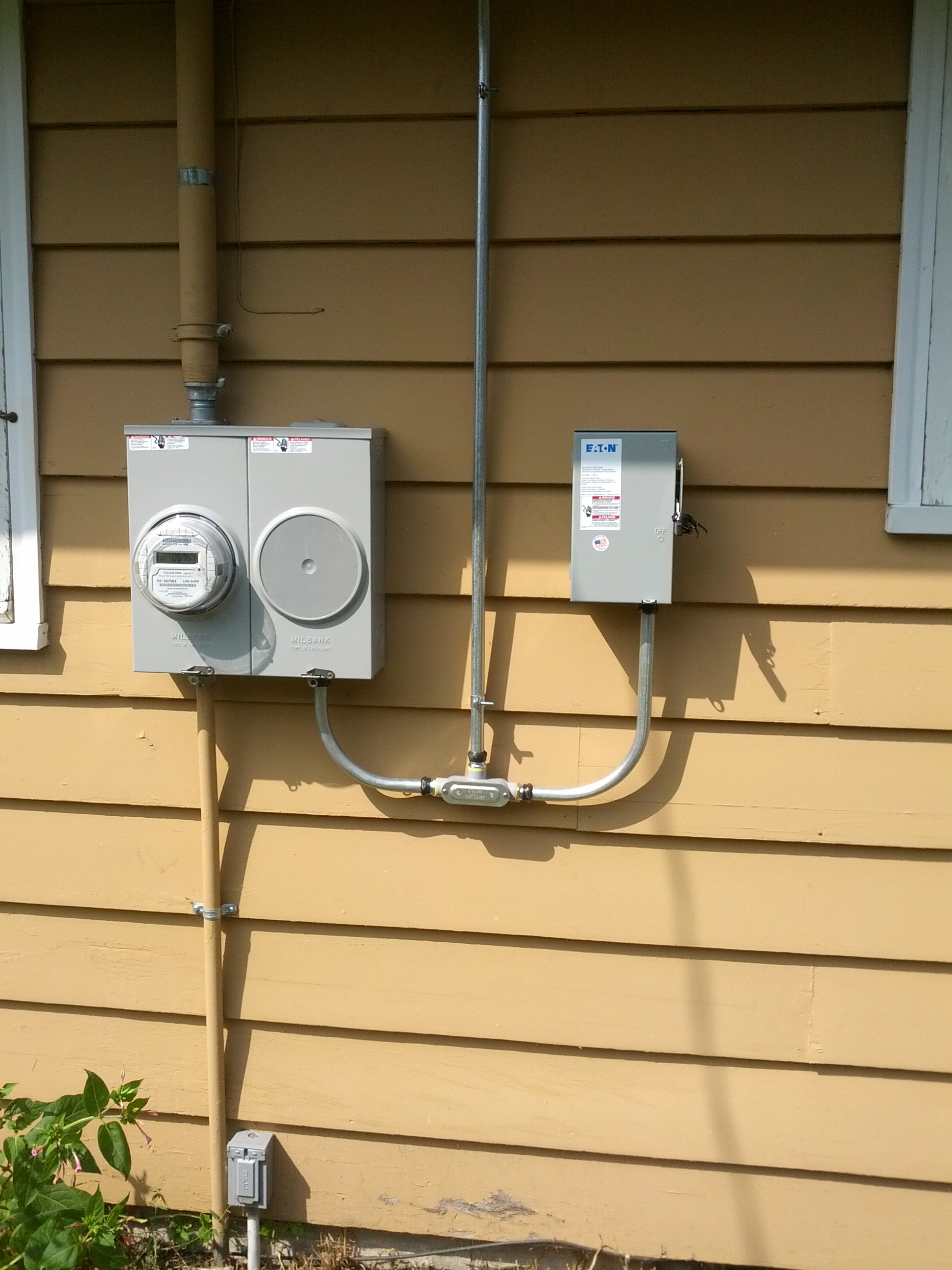
The inspector and my contractor showed up yesterday and the setup breezed through inspection.  Having a parallel PV installation was key here since it split out the existing residential/expense side of my electrical installation from the new commercial/revenue side.

As it turns out, electricians and even New Berlin electrical inspectors themselves have separate residential and commercial groups.  Because our 1kW array is a revenue earning installation, the inspector was from the commercial side of the house and his task was simply to evaluate the PV portion of our dual meter installation.  Had we gone with a serial PV setup (where the solar array is connected directly to a breaker on the main panel), then both groups would have been involved at all points of the project.  In this scenario, the same tasks could have taken twice as long to accomplish due to the additional level of coordination required.  Parallel installations are definitely the way to go!

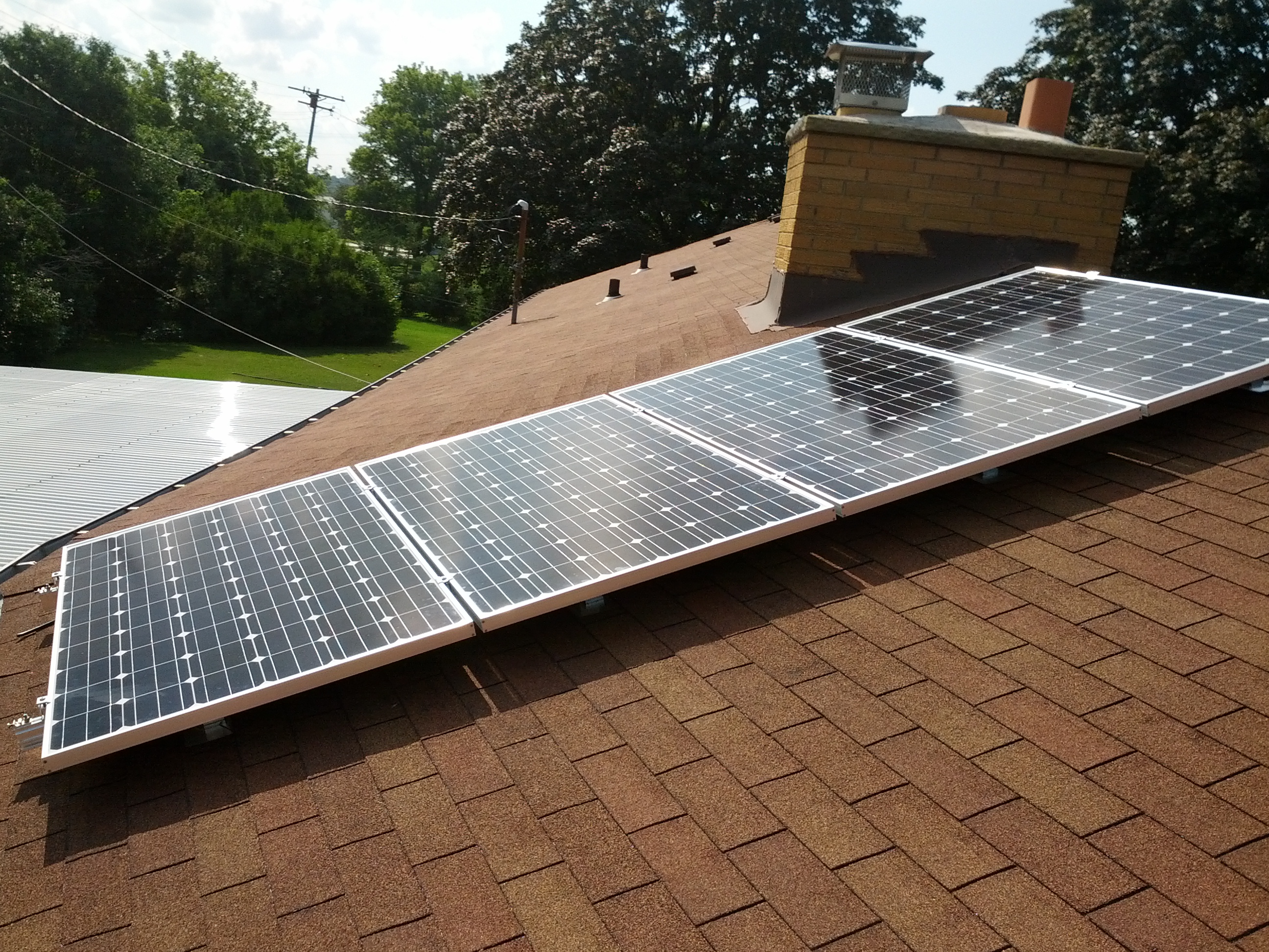
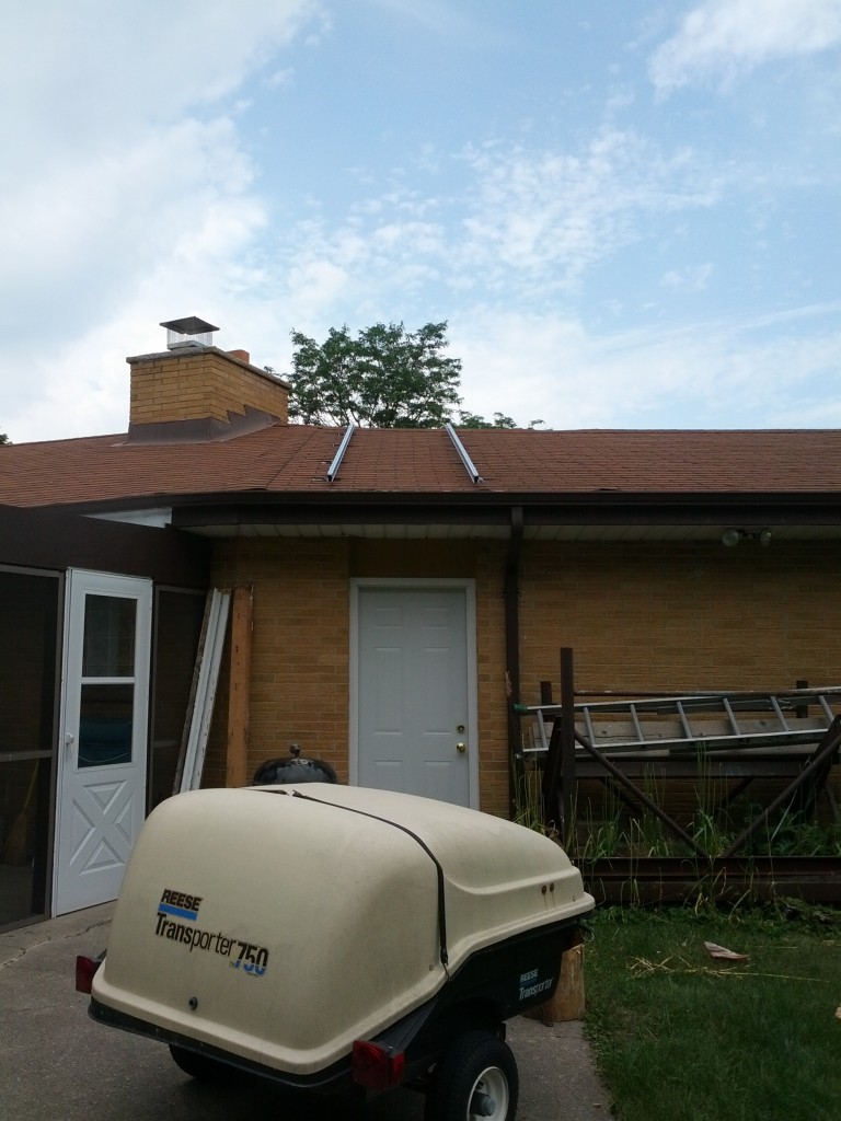
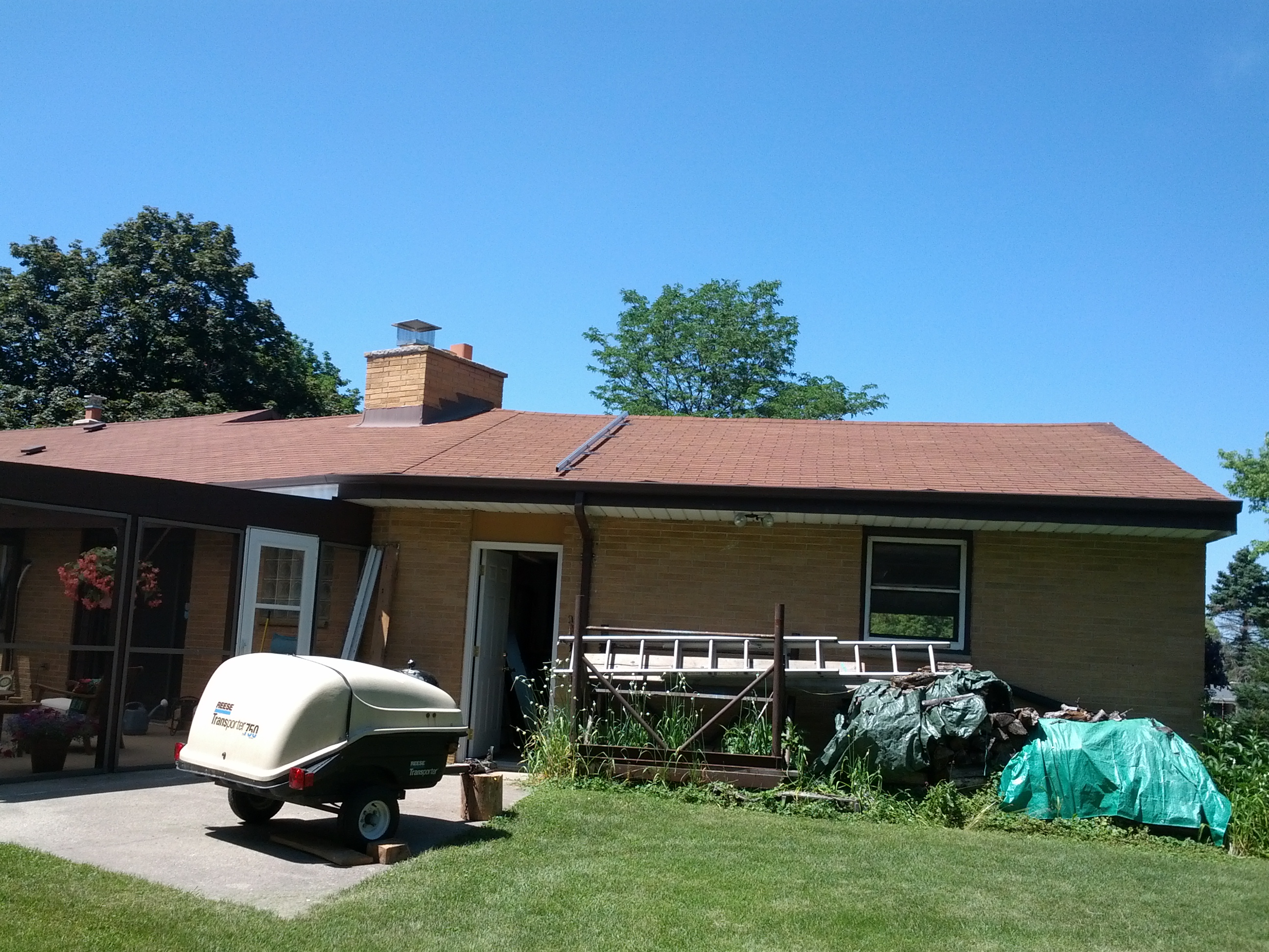
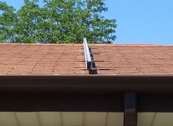
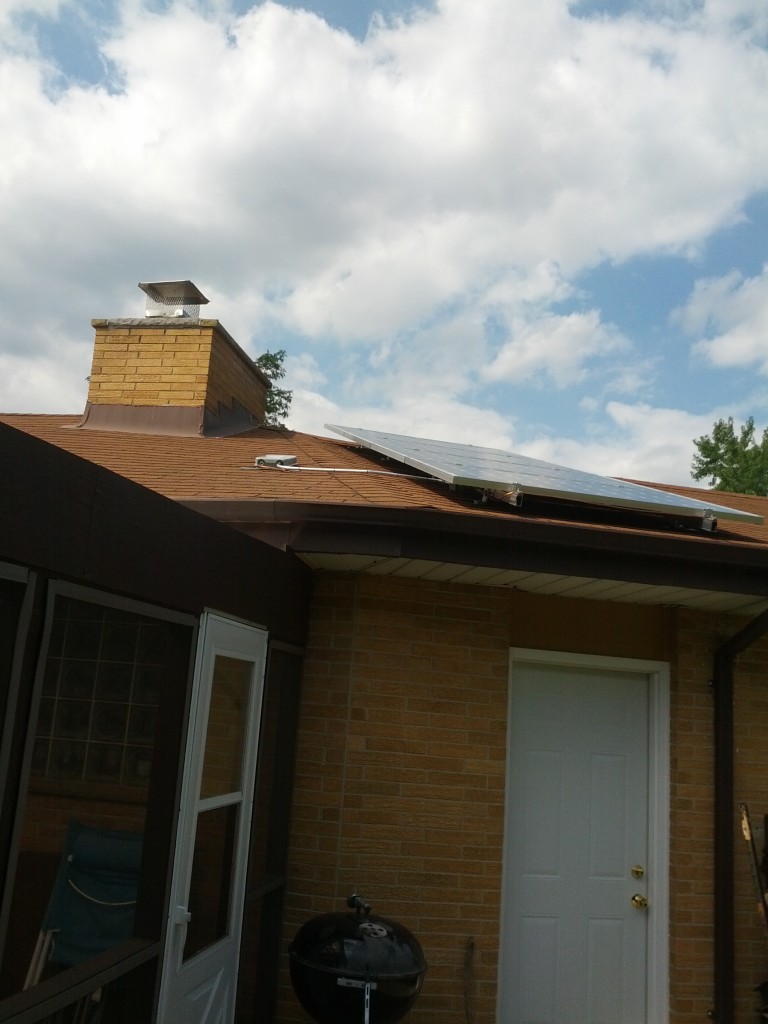
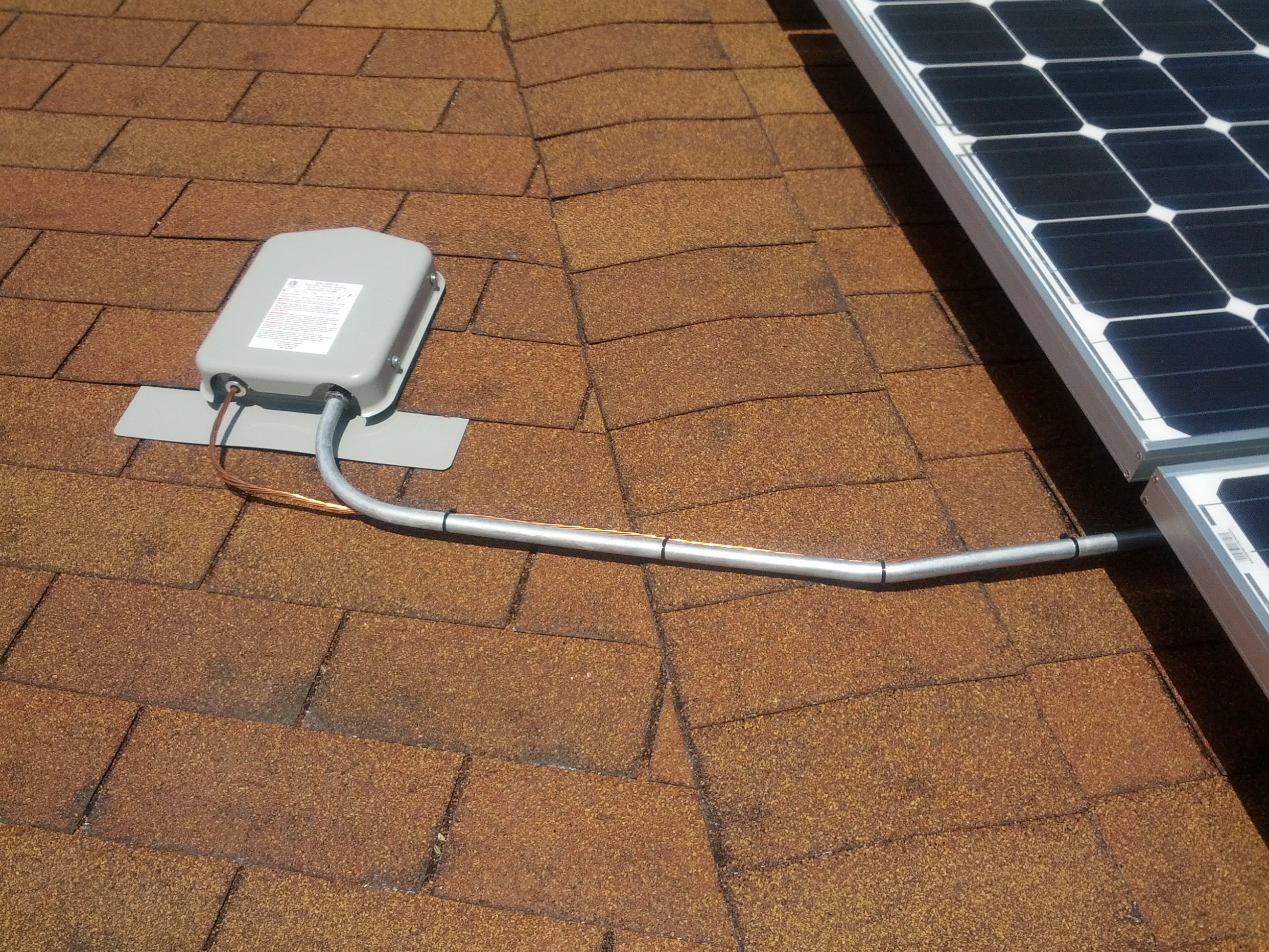
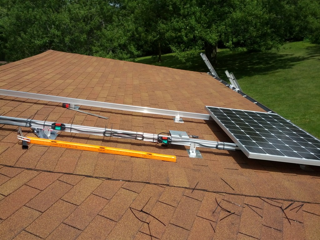
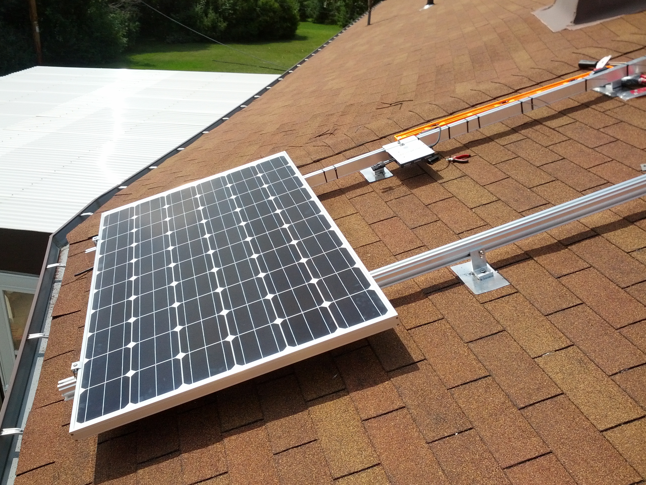
Our inspector was also quite impressed with the level of standardization on the roof.  This was the first time he had inspected an Enphase M215 micro-inverter setup with engage trunk cable on standardized Renusol racking, and he quickly caught on to the implications.  He even asked for cut sheets on the new inverter/racking technology for his personal records citing that this could “open the sluice gates” for home PV installations.

I couldn’t agree more.

So, what happens next?

  • The inspector will inform our WE Energies contact person that the configuration is ready to commission.
  • Somebody from WE Energies will be out before Friday to install the PV generation meter
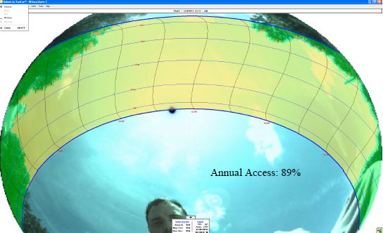
  • WE energies will show up on the afternoon of 9/13 to commission the system.  Essentially, they will turn everything on at the disconnect, verify that it powers up correctly then (most important part), turn it back off to make sure the inverters shut down within 2 minutes.  This test proves out the system’s the anti-islanding capabilities.
  • Sometime in the future, a lineman will be out to replace the temporary splices at the service entrance weatherhead with their own.  Interestingly, my contractor told me that it could be months before they got around to it.  He also said to make sure they give back the current splices since they are apparently worth quite a few bucks on eBay…

On my immediate task list:

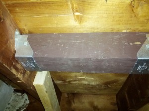
  •  Install a second TED5000 CT in the 6″ attic box and connect up to my TED5000 system.  This circuit tap will measure PV output and allow my TED to precisely track overall PV system performance over time.  I’ve ordered this component already and it should arrive sometime next week.
  • Extend the computer room branch circuit up to the attic to provide connectivity to the TED CT.  This will require BX armored cable and may be a bit of a pita since the cable itself will go up the chimney enclosure.
  • Purchase 2 DIN mounted SPs to protect the array against lightning surges as well as a new Panel mounted SP to protect my extensive UPB installation.
  • Fill out the Focus on Energy rebate form just as soon as I get the bill from my contractor.  My deadline to accomplish this is October 10th.
Posted in Energy, Solar | Comments Off

Completed installation; we are ready for inspection!

My contractor has finished the array connections and a nicely done piece of work it is too!  Here’s a few shots of the roof mounted junction box:

The box itself contains a DIN rail that can be used for surge protectors.  I’ll install these when the other 12 panels go up.  The other end of the half inch EMT conduit terminates on a Bell weather tight box under the panels.  What’s nice about this is that I can simply extend the Enphase engage cable out to the next racks or I can choose to terminate more cables in the Bell junction box.

Here’s the completed disconnect:

My contractor also installed a 6″x6″x8″ box in the attic.  The vertical conduit terminates there along with the 20′ horizontal run.  Wires were pulled straight through this box then the hots were looped inside.  This will be where my TED5000 circuit taps will connect.  I’ll need to run BX from the computer room box up there myself to extend the TED signal carrying branch circuit (which is isolated from the rest of the house with an X10 filter).

I’ll do this after the array is commissioned.

We are almost generating power now!  my next milestones are:

  • 2:15PM electrical inspection on the 5th.
  • commissioning the system with WE energies (TBD)
Wish me luck for a trouble-free inspection!


Posted in Energy, Solar | Comments Off

Installing panels and inverters.

With the panels finally on site, it was time to get down to their actual installation.  First, I needed to mock up the inverter/panel position to derive a measurement template.  As it turned out, the inverters could be mounted directly below and at the midpoint of each panel, and the Engage cable coupler could be mounted directly above it.  Taking the renusol inter-panel connectors into account, this made for 39″ between the bottoms of each panel, 25″ from the bottom of the panel to the inverter center, and 28″ from the bottom of the panel to the engage connector center.  You can see the alignment in the pics below:

After I had the measurements, I marked them all out on the west rail with a blue sharpie.  Then it was time to actually begin the assembly process itself.

My first installation step was to run the enagage trunk cable along the outside of the rail with connectors facing west.  The idea behind this was that the 120v connector from each inverter would be run over the top of the west rail and left loose, to be connected up when the rest of the 120v wiring to the dual meter base is complete.  The cable connectors’ west facing orientation would make them easily accessible once everything was ready.

Unfortunately, the cable was also incorrectly ordered for landscape, not portrait orientation so the distance between connectors was 67″ instead of 40″.  This is why you can see that I’ve looped and wire-tied the excess to the rail.  The wire-ties themselves were UV resistant and designed for outdoor use.

The first panel took the longest because it needed to be correctly aligned to perpendicular and centered on the rails.  After that, it went pretty fast because each subsequent panel was simply aligned to the panel underneath.  Essentially the process became:

  • Mount the inverter using a WEEB-CCR grounding washer between it and the rail and torque to 12ft lbs.
  • Run the panel up to the roof and lay on the rails.  We used two ladders for this so that Angel and I could go up together with the panel suspended between us.
  • Connect up the panel’s DC cables to the DC side of the inverter.  This powered up the inverter.
  • Double check that the inverter status LED went to flashing red (not producing AC) after about 5 minutes.  Since these are grid-tie inverters, they will not produce AC if they don’t sense an existing AC signal on the grid itself.
  • Center/torque the panel to the rails using renusol connectors

We used WEEB-CCR grounding washers for the hardware between the first and second panels and also between the third and fourth panels.  Here’s what a WEEB-CCR looks like:

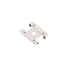
These sit right on the top of the rail between the rail itself and whatever hardware is being mounted on it.  When torqued to spec, four sharpened nubs on each end of the WEEB dig into the mounted hardware on one side and the rail on the other side.  This forms a solid ground connection that is impervious to weather related corrosion.

With our installation, 8 WEEB-CCRs were required to form a complete grounding solution: four for the inverters, and two sets of two between panels.

By 4PM, we were done!

At this point, the 1KW installation is almost complete!  Our final task will be to connect up the AC side to the meter.  Next up, my contractor will be in to complete this in the following order.

  • Install a disconnect switch by the meter
  • Run conduit up into the attic and connect it to a 6×6 junction box that is itself connected to the horizontal conduit run I did earlier.  This box will contain the CTs for my TED5000 energy monitor and allow me to monitor electric production from the array.
  • Mount a junction box on the roof near the array.  The one we will use will actually be flashed into the roof itself.
  • terminate the engage trunk cable on the west rail using a weatherproof junction box, then run 1/2″ EMT between it and the roof mounted box.
  • pull #10 wire from the disconnect to the roof box and connect up.

Plans are to complete this on Tuesday, 8/13 and Wednesday 8/14.  When finished, we will be ready for inspection/commissioning!  Stay tuned!

Posted in Energy, Solar | Comments Off

Installing the second Renusol rail.

The weather was nice and cool last Sunday; perfect for working above the garage, so I installed the second Renusol rail.  This one would be a bit trickier than the first because the rail itself landed between two rafters.  To make sure the anchor points were sufficiently engineered to withstand roof wind/snow loading, 4×4 cross braces would
be used at each of the four anchor locations.

Here’s a shot of one.  Simpson strong-tie SD structural screws were used on the hangers since swinging a hammer was virtually impossible in the confined space above the garage.  These #10 screws are pretty awesome; With their self tapping ends, they go in with virtually no force at all.  I’ll be using them everywhere in the future!  Two lengths were needed: 1 -1/2 inch screws went into the face connections and 2 – 1/2 screws were used for the toe-in slots.

On the top of the roof, I first marked 40″ off from the middle of the right side top and bottom bracket mounts (40″ is about 1000mm which is the on center distance between panel mounting holes) then made tape marks.  Next, I once again used the rail itself as a giant straight edge to line up the other two mount points.  Then, I measured down from the top of the shingle directly above each mark to determine the mounting location.  This ended up being 1 – 3/4″ to make the edge of the flashing about 1/4″ above the edge of the shingle underneath it.

In the photo above, you can see the flashing piece itself  which illustrates the 1 – 3/4″ offset requirement.

Once marked, assembly proceeded pretty much identically for each mount point:

  • drill a small pilot hole and insert a coat hanger
  • locate the coat hanger below the roof and install the cross brace
  • back on the roof, widen the pilot hole to 1/4″ and extend to 3″ depth, then position the Ecofasten flashing.
  • Fill the 1/4″ pilot hole with roofing mastic and position the sealing plate and the “L” bracket.
  • Ratchet down a SPAX 3/8 x 5″ HCR lag (HCR is their high corrosion resistant coating) but leave loose.

Finally, position the rail on the L-brackets, double check that it is parallel to the right side rail, and torque to 140 inch/lbs.  Finished!

Next up, my contractor and I do the following:

  • wire up the second meter slot, install a disconnect and complete the conduit run from the disconnect to my horizontal run in the attic.
  • Attach the roof mount junction box onto the roof itself and run conduit from there to the other end of my horizontal run in the attic
Then we wait for the solar panels to arrive and make final connections.  Stay tuned!
Posted in Energy, Solar | Comments Off

Things keep rolling along… dual meter base installation!

The project reached several important milestones last week!

First was the double meter base installation that was completed on the 22nd.  Everything got underway at about 8:30AM when I started up the genset to power the house electronics/server systems for the extended outage.

This portable system puts out 5000 watts maximum and easily powered the home systems/server farm which draws a constant 600 watts.

Once everything was running, the electrician pulled the meter to shut down the house, then flipped all the breakers off.  Then he cut the POCO wires at the weatherhead.

The new base was quite a bit taller than the original, so the plan would be to lift the service mast up to accommodate, increasing the height of the weatherhead itself about a foot or two.  Since the mast was simply sealed with mastic at the roof, we had to first carefully loosen it up so that roof shingles wouldn’t go along for the ride too.

Here he is working on the weatherhead.  You can see the glob by his feet where the service mast was sealed.  The original meter base is still in place too.

The next step was to lay out the new meter base, double check the fit and install conduit fittings.  Once that was accomplished,  the old base could be removed and the new one installed.

When he got the base apart, I got my first bad news: the conductors from the main panel were too short and needed replacement.   That was a bit of a bother since my panel has three grandfathered in code violations: The service entrance is underground and feeds into the back of the panel, the bonded grounding system isn’t attached to our municipal water feed at its own service entrance (below the meter),  and the front panel access itself is recessed about 2″ behind the sewing room wall.

Because the conductors were new, the main panel now needed inspection and this meant that the inspector, if he wanted to, could call out the three existing violations requiring me to make extensive (spelled “expensive”) modifications to correct.  Hopefully, this won’t be the case….

Anyway, once assembled, the electrician got up on the roof and lifted the service mast up while I slipped in the new base.

The result can be seen here.  Everything looks pretty good at this point!

Next the electrician ran new service mast wires and installed a new weatherhead.  Then he re-spliced the POCO conductors.  This is done hot, so he wore big rubber insulating gloves while he installed the splices.  Interestingly, once everything passes inspection, WE energies will be notified and they will send out a lineman to install their own splices and place a seal on the meter.  I’m not really sure why they do this, since the electrician’s splices looked identical.  Bottom line: I pay double I guess.

Everything was pretty much complete at this point, so the electrician re-installed the meter, inserted a plastic cover for the soon-to-come second meter and switched on the breakers.  Finished!

Posted in Energy, Solar | Comments Off

The wait is over! Construction progress…

A lot happened this week!  The Pieper residental group electrician stopped by with a dual meter base on Thursday but it was the wrong size.  Our meter comes in right next to a window so a single hub dual meter (which has the poco feed at the top center) won’t cut it.  Instead, we need a dual hub version that can have the PoCo service entrance on the left side:

My contractor found this Milbank dual socket which should fit the bill nicely and they’ll be back out to install it soon.

Werner electric also dropped off the roof rack components so I got to work.  Installation is pretty simple once you’ve determined the exact rafter location.  Simply place one of the special EcoFasten GF1 flashings under the shingles so that the lag bolt sealing hole is lined up with a 1/4″ pilot hole (drilled into the rafter and pre-filled with roofing mastic), then install a 7/16 x 4″ lag bolt through the flashing, top sealer plate, and the lower slot in the Renusol “L” bracket.  I wasn’t real pleased with the way that the specified lags gripped the rafter however, so I used 5″ SPAX lags instead.

What’s nice about these lags is they way they self tap into the rafters without splitting.  Since these are designed for decking ledger boards, they can also handle both horizontal and vertical sheering forces.

There’s no way these lags will be dislodged by just about anything WI weather can throw at us.  They easily torqued to the specified 140 inch/lbs as well.

With the “L” brackets in place but still not torqued down, the Renusol VR rack was easily mounted then adjusted to vertical with a carpenter’s level.  Then, I torqued the 4 lag bolts to specifications.  Finally, I went up into the garage attic and carefully inspected rafter #14 to be sure I hit the center marks correctly.  It was easy to see the mount positions because mastic had seeped out between the decking and the rafter itself when I torqued the lags.  It was perfect; no splitting anywhere, and no lag bolts were sticking out either!

Finding the rafter is an interesting challenge though.  What I did was drill a tiny hole in the middle of the roof at the position I previously calculated the rafter to be,  then I stuck a piece of coat hanger through so I could find it from below.  Turns out I was exactly 1 1/2″ off from the center of the rafter itself.  Now with the exact rafter center mark scribed on a piece of masking tape attached to the roof, I used the Renusol rack as a huge straight edge and adjusted it to the same vertical as the underlying rafter with my carpenters level.  Do this by first checking the vertical orientation of the rafter itself from below and then adjust the renusol “straight edge” to the same bubble offset from level (if any).  With the rack adjusted, it was easy to mark the drill positions for the mounts.  Don’t forget to fill in the exploratory hole with roofing mastic!

By the way, don’t be tempted to use the roof shingles themselves to line everything up.  The picture below says it all!

Well that about wraps it up for the weekend.  Next Saturday, I’ll install the left side rail.  This will much more difficult because it doesn’t land directly on a rafter.  Instead, I’ll need to install a 4×4 cross brace at each mount location then attach to those.

Coming up:

  • The Pieper residential electrician will install the dual meter base, and my contractor will install the disconnect switch then bend a tricky bit of 3/4″ EMT between it and the horizontal attic run that I previously installed.
  • He will also install the roof mounted junction box (which is actually flashed in) then bend another tricky bit of 3/4″ EMT between it and the other end of my horizontal EMT run.
  • Pull #10 wiring, and mount panels/inverters once they arrive.

Hopefully I’ll be able to assist with all of these tasks, so stay tuned!


Posted in Energy, Solar | Comments Off

Solar project update

We got plan approval and the go-ahead to build from WE energies last week!  I also filed my grant paperwork from this site after calling the listed number and being told that grant funds were still available.

The weather was pretty cool last week so I took the opportunity to run 20′ of 3/4″ EMT between the second meter location and the spot on the roof where the array junction box will be placed.  I then fine-tuned the roof rack location so it would land exactly on a rafter on the right hand side and tested a ventilation technique that promises to reduce heat build-up in the garage where we will be working.  I wasn’t too impressed with the results; it really looks like I’ll either have to do the work in the early morning hours or plan on roasting up there….

So now I’m waiting.  Waiting for Renusol VR panel racking components to be dropped off.  Waiting for my 265W Suniva panels and enPhase microinverters to arrive.  Waiting for the my contractor’s residential electricians to call me about installing the second meter.

I hate waiting…

Posted in Energy, Solar | Comments Off

SunEye report and more prep work.

Our contractor arrived last week with his SunEye and did a full shading workup of the roof.  Essentially he measured 6 points on the roof as shown here:

The important measurements for this year are locations 1 and 2 since this is where the initial array will be built.  And, for six hundred dollars in WI Focus on energy grant money, the answer was this:

and this:

That’s within the 10% minimum shading requirement!

So, why the difference?  Essentially, SolarEye can spot trees and adjust the calculation accordingly.  My analysis was a “worst case” analysis that treated trees essentially as a concrete barricade that had the profile of my shaded area line.

After I receive my contractor’s invoice for a $500 downpayment, I can fill out my grant reservation for a $600 cash rebate.

We’re also going to go with Suniva 265 Watt panels because the OPT270s are oversold through August.  My cost for those will be $324.88 each (delivered).

Hows the budget looking?

1,299.50 (panels)
2,350.00 (contractor)
600.00CR (focus grant)

= 3049.50 for the 1KW array. Not too bad!

Posted in Energy, Solar | Comments Off

The Bottom Line on the initial install.

The estimate is in and its $2350 for the initial hookup minus the price of the four solar panels themselves.  For this price, my contractor will provide the following:

  • Renusol Racking and components for (4) modules (material only).
  • (4) Enphase M215 micro inverters and associated trunk cabling (material only).
  • (1) Double meter socket (100A rated) (material only).
  • (1) 250V, 30A Fused disconnect (material only).
  • Permitting costs and assistance with interconnection and possible incentives (material only).
  • Associated wire, conduit and material as necessary.
  • (24) Hours of onsite labor and technical assistance

I’m going to be tapped for most attic/garage work starting with an EMT conduit run from the attic POCO weatherhead to the lower left side of the array.  I’ll also be installing the Renusol Racking components themselves.

My contractor will put in the double meter socket, handle grounding requirements, pull wires and oversee any work that I do.  We will both install the panels themselves once they show up.

Speaking of panels, I’m vacillating between the Suniva OPT270 (ideal but scarce currently due to demand), OPT265 (contractor supplied at a decent price but also subject to availability) and Helios 265 Watt panels which are made locally right here in Milwaykee.  They have an open door policy so I’m thinking I’m going to drop by the factory and have a chat with them.  I can potentially save on substantial shipping costs with these guys if I can just purchase and pick up myself. The biggest issue may be finding four of them for a reasonable price.

Bottom line for the initial installation will come in between $3600 and $4000.  On the 18th we’ll go over the details.


Posted in Energy, Solar | Comments Off

Contractor discussions, DIY tasks and Derate Factors

Well, we met our Solar contractor today and yeah…. he’s a geek right down to the Nikola Tesla is his hero part.  More importantly, we’re both on the same page concerning the installation.  He has no problems letting me save $$$ by doing parts of the job myself so I’ll probably do the array mounting rails up on the garage roof, run the electrical conduit from the panels to the meter base and help install the panels themselves.  Working in a hot attic is no fun but if the weather stays cool the attic won’t get too bad.  I’ll just run a big cooling fan or do it at night if it does.

I’ve decided on our panel manufacturer too.  I’m purchasing high performance mono crystalline 60 cell panels from Sunivia, a company located in Norcross GA.  These guys use high-tech automation to manufacture some of the most efficient panels on the market and, because its all automated, their prices are great too.  I’m going with their OPT270 line which are 270 watt, 60 cell panels that cost $320 each delivered.  The increased wattage will drive the enphase micro inverters better in low-light/shaded situations too.  Since each inverter produces 218 watts, the initial 4 panel array will then be capable of producing 872Watts @ 240VAC from a combined 1080W DC input.  This difference is known as the “derate factor” and is based on inverter efficiency, wire coupling losses, and resistance.

I’ll be purchasing the panels/inverters/mounting hardware directly and my contractor will guide/inspect any work that I do and also handle the main electrical hookup work.  That includes installing the double meter base and pulling wire through the conduit that I run.  He will also pull permits and help out with WE energies paperwork if I get stuck.

He’s going to get me an estimate next week with DIY options laid out.  He will also do a quick Solar Pathway analysis of the site to see if he can validate my numbers which ended up being a bit high at 20.54%.  Since his software can account for the varying shade factor of deciduous trees, it’s likely that he can hit a better number than I did however.  Still, I’ll be quite surprised if he tweaks it below 10% to qualify me for the WI focus on Energy subsidy…

Speaking of Solar surveys, here’s my final analysis which I verified by actually watching the shading factor on the roof at sunrise/sunset:

The times shown are CST.  The 20 degree shade area at the left are two silver maples in the side yard and the similar area on the right are two red maples in the other side yard.  I actually took elevation readings every 10 degrees from 60 – 320 then inputted the data into Solar Shading, a cool Android app that did the shading calculations.  At $14 its a bit steep but it does produce a very nice report showing not only a graph like the one above, but also several bar graphs showing shading factor/power output by month.  It thinks we have a 20.54% shading factor but only a 5% power loss factor since the main shading areas occur in the morning and evening hours when the array isn’t producing much power anyway.

Stay tuned; I’ll be chatting about my options next week when I get my job estimate back.  I’m pumped to get this done before the Solar Solstice :)

Posted in Energy, Solar | Comments Off