How to do a Solar Survey

PVWatts is a good tool that uses average sunshine data to predict solar collector efficiency, but there’s another important factor to the equation: shading.  Once you determine the shading factor, the PVWatts data can be multiplied by the sun percentage to more accurately predict energy output.  The idea here is to find the best spot on your property to mount your solar array.  In some cases, once a Solar survey is completed, it may even become clear that solar isn’t a practical solution.

So, on to the survey.  This is actually a fun exercise that doesn’t take too long to accomplish either.  First, you need to determine true south.  This is a pretty easy task that leverages “solar noon” or the point during the day where the sun is highest in the sky.  At that time, any shadow from a vertical object points true North/South.  NOAA has a cool calculator that allows you to determine the exact time of day that solar noon occurs for the proposed solar site too.  It’s called the NOAA Solar Calculator and its pretty easy to use.  Just zoom the satellite image to your proposed site and drop the large pin on the exact location.  Voila, solar noon is displayed!  There’s other cool stuff you can display too such as the sunrise and sunset angles.  These are the red and green lines shown on my image above.  What you want to do with these is to first change the date to display for the summer solstice then note the obstructions.  In my case, you can see the two maple trees to the left and right of the house along with  the woods behind me are potential shading factors.

Next, you need a plumb bob whose line will cast that vertical shadow in a true north/south direction at noon.  In my case, I adjusted the plumb bob so the shadow cast by its line fell on the garage wall and across the patio floor.  I then placed a protractor against the wall so that the shadow cast by the line was centered.  The protractor now read out the sun angle in relation to the garage.  At 12:50:02, I simply read the angle off and adjusted from 180 degrees.  Mine showed exactly 20 degrees West (right of center) which means that my array will face at 160 degrees.  This was pretty much a verification of my original estimate.

Before closing the calculator, make a note of the latitude/longitude displayed because we need that for our next exercise which is to obtain a Sun Chart for the proposed site.  Sun Charts are available here: http://solardat.uoregon.edu/SunChartProgram.html .  Just enter the latitude/longitude from the NOAA calculator, use default settings for everything else, download the pdf version of the Sun Chart, and print it out.  The Sun Chart shows the position (azimuth and elevation) of the sun for every minute of the year — all on one piece of paper!  It is worth spending a few minutes studying the Sun Chart, and understanding how it works.  It’s a great way to check your understanding of the movement of the sun in the sky throughout the day and the year.   Here’s mine:


Now comes the fun part,  plotting your shaded areas on the chart to get a visual representation of the total shading factor and allow you to estimate the shading percentage.  You will first need to make gauges to measure the sun azimuth and elevation angles.  Download this Solar Elevation and Azimuth Gauge, and print out two copies of it.

Make the Elevation gauge

  • Paste one copy onto a piece of cardboard.
  • Trim the cardboard along the Site Line (you will site along this edge for elevation measurements)
  • Put a small nail through the center of the Reference Circle where all the lines meet
  • Tie one end of a light string to the nail, and the other end to any small weight (e.g. a bolt or nut)

Make the Azimuth angle gauge

  • Paste the other copy onto another piece of cardboard.
  • Find a thin, straight piece of wood (e.g. a wood pencil) and drill a small hole near one end.  You will site along this pointer to measure azimuth angles.
  • Put a small nail through the drilled hole, and then through the center of the reference
    circle.


Now that you have the two tools you need, go to the center of your proposed solar site and plot a dot showing the top of visible shade every thirty degrees on your solar chart.  Start at the leftmost blue line on the chart and end at the rightmost.  Essentially, adjust the angle of the azimuth gauge then look along the line shown.  Now sight along the top of your elevation gauge to the top of any obstruction that can be seen.  Read out the angle and plot the point on the sun chart.  When finished, simply connect the dots and you will obtain a visual representation of your shading factor.  I haven’t done mine yet; its a weekend project but here’s an example of what a completed sun chart with shading factor looks like:

It’s pretty easy to estimate the total shading factor now.  Remember, you really want no more than 10% total shading on your graph.  In fact, if you have more than 10% then you may not qualify for any solar related rebates or incentives.  Also remember that trees create shade in the summer and aren’t necessarily a factor in the winter.  In the chart above, the big bump at the left is a tree which really won’t affect the sun in February.

Have fun doing your own solar survey and stay tuned for more on our own installation!

Posted in Energy, Solar | Comments Off

Solar project progress: Surveys and Rebates

There are a number of tools out there to help plan a PV installation. One of the most useful is the PVWATTS solar energy calculator.

PVWATTS uses nationally compiled solar survey data to estimate location specific energy production based on array efficiency, panel orientation, and tilt.  In our case, the planned 1KW test array will generate about 1280KW/year with a fixed roof mount.

Of course, since this is an experimental system; my goal will be to develop a mounting system that allows periodic panel re-orientation to the seasonally adjusted sun angle.  This “1-axis” tracking system will rotate the panels back and forth about 40 degrees throughout the year.  Since the entire yearly rotation factor is only about 80 degrees, no costly mechanical engineering will be required.  I’m thinking that I’ll be using either a u-bolt arrangement or a beam attachment with holes drilled through the center.

The energy gains from this simple design change are impressive however.  As can be seen below, a 1-axis tilt system provides an energy output boost of about 20%.  Not bad for a system that only needs to change panel tilt by a few degrees each month!

The plan to accomplish this will be to mount the panels in a “landscape” orientation so they can rotate around a horizontal mounting shaft that is anchored about three inches off the roof at every rafter.  Since this will be the only anchor point for each 40 pound panel, it will need to withstand 90MPH wind gusts and 30″ of snow cover on its four connected panels.

I’m planning on an extended design/test cycle to solve this engineering challenge, so our initial mount plan will be to use the Renusol VS fixed mounting system and orient some of the anchor points at the middle of each panel to facilitate a future upgrade once the rotational system has been appropriately tested and qualified.

The array location will be our south facing garage roof.   As can be seen in the picture below, it provides 15ft by 24ft of uninterrupted space that is perfectly sized for a four by four landscape array.

While its 160 degree orientation isn’t optimal, the roof itself is re-enforced by a large structural support beam that was added to facilitate overhead storage in the garage.  This feature is also a bit of good fortune for us since the weight of our final 4KW installation will exceed 800 pounds.

The roof area is just about completely unshaded too which is critically important to a PV solar system.  In fact, most rebates and incentives for Solar Energy production specify that the location can have no more than a 10% shading factor.

Here’s the overhead CAD view for the final 4KW installation:


It’s pretty easy to see why solar panels now use pretty much standard dimensions of 40″ x 64.5″ since this lines up almost perfectly with 16″ oc rafters.  There will be two vertical mounting rails per four panel group that will each support about a third of the combined array weight.  Our initial installation will build out the leftmost panel group.

WE energies, our electric service provider, requires a 2 meter system to run our grid tie array.  They will net the difference between the readings and pay us about 4 cents per KW if we generate more than we use.  This will be credited towards next month’s bill.  If, at the end of a yearly period ending in May, we still have a net credit then they will send us a check.  However, we will only qualify for the program if we can submit data showing that this isn’t likely.  Acceptable proof will be last year’s energy data and our PVWATT estimate.  WE energies also requires a 300,000 dollar liability insurance policy against potential grid damage caused by our generation facility with a current certificate of insurance on file at their offices.  I checked with our home insurance provider and they stated that the liability clause of our standard home policy covers this hazard.  All I need to do is inform them where to send the certificate and they said they would take care of the rest.  Nice!

So how’s the construction cost factor looking?  Our initial estimate for the fully installed 1KW system is about 5-6K.  We will be eligible for a 30% federal tax rebate along with a $600/KW rebate from the Wisconsin focus on Energy program.  Based on this, I just may decide to start with a 2KW system since the rebate check will pretty much pay for the next four panels….

Our next milestone is May 31st when we meet with the contractor to discuss installation details.  Stay tuned!


Posted in Energy, Solar | Comments Off

We’re going Green!

These days, prices on Solar power panels have been dropping like stones while the technology to use them as well as the connection/mounting standards to install them have been advancing at “Warp Factor Nine”.   Of course, these rapid advancements are due in no small part to our country’s current focus on clean, renewable energy sources but until now it had all seemed just like political rhetoric to me.  Well, not any more!

Anyway, I’ve been tracking this technology for years but decided to pull the trigger when I learned about the new M215 Enphase microinverter along with their innovative “Engage” cable system.  These two products leverage the current solar panel standard which is 60 cells @ 250W to form a modular, cost-effective grid-tie interconnect system for Solar power generation.

I’m currently spec’ing out a 1KW grid-tie solar array for the house that will be based on Wholesale Solar’s 1KW starter kit. It’ll fully leverage the super efficient M215 Enphase microinverter design and features 4 standard 250W 60 cell panels.

The plan is to get the main infrastructure built for a 6KW capable system (20Amps @ 240V) and put up the Solar kit for about 5K total including installation. Then we will run the system for a year and monitor power output with my existing whole-house system.

During that time-frame, we’ll experiment with 1 axis tracking, auto snow removal, and generally learn the basics of distributed power generation. Then we’ll take advantage of falling prices to expand out in subsequent years. Our final installed size will be 24 panels and the incremental costs would be panel price + about $25 per panel for mounting/cabling. The new Enphase engage cable system along with Renusol’s modular racking system is key to this low cost expansion rate.  Right away, this 4 panel starter system will provide about 1.5KwH per year of fully renewable green energy to the WI grid.

I’ll be posting much more as the project progresses including videos of the installation process itself.  I couldn’t be more excited!

Posted in Energy, Our Fragile Planet, Solar | Comments Off

Using Sunlight to increase the energy output.

This bridge technology can increase the fuel efficiency of NG fueled power plants by 20% on a sunny day!

Source: txchnologist.com
Publication date: April 12th 2013

By Michael Keller

Scientists Inject Sunlight Into Natural Gas For Bigger Bang

Scientists Inject Sunlight Into Natural Gas For Bigger Bang

Government researchers have figured out how to add sunlight into natural gas to boost its potency.

Using a concentrating solar collector to inject the sun’s power into natural gas, Pacific Northwest National Laboratory (PNNL) scientists can now convert the standard fossil fuel into higher-energy syngas.

They say the system lets power plants use about 20 percent less energy when the sun is shining while producing the same amount of electricity.

“Our system will enable power plants to use less natural gas to produce the same amount of electricity they already make,” PNNL engineer Bob Wegeng, who is leading the project, said in a statement. “At the same time, the system lowers a power plant’s greenhouse gas emissions at a cost that’s competitive with traditional fossil fuel power.”

image

(PNNL’s concentrating solar power system for natural gas power plants, installed on a mirrored parabolic dish.)

A mirrored parabolic dish concentrates sun rays onto the system, composed of the collecting mirror, a chemical reactor and several heat exchangers. The solar energy heats natural gas in the reactor, which also contains a catalyst that converts the fuel into syngas with a higher energy content. Tests run on an early prototype of the system showed that 60 percent of the solar energy hitting its collecting mirror was converted into chemical energy in the form of syngas generation.

They next plan to run field tests on the device at PNNL’s Washington State campus.

image

(PNNL’s thermochemical conversion device is installed in front of a concentrating solar power dish. The device converts natural gas into the more energy-rich fuel syngas, which power plants can burn to use less fuel and reduce greenhouse gas emissions.)

All Images: Courtesy Pacific Northwest National Laboratory.

Posted in Energy | Comments Off

Another Capacitive battery hurdle crossed!

 I uncovered this while browsing the web earlier today.  I’ve always felt that capacitive batteries will become the ultimate energy storage device.  Now, they can be mass produced.

Source: UCLA Newsroom
Publication date: February 19th 2013

By David Malasarn

Micro-supercapacitor

Kaner and El-Kady’s micro-supercapacitors

While the demand for ever-smaller electronic devices has spurred the miniaturization of a variety of technologies, one area has lagged behind in this downsizing revolution: energy-storage units, such as batteries and capacitors.

Now, Richard Kaner, a member of the California NanoSystems Institute at UCLA and a professor of chemistry and biochemistry, and Maher El-Kady, a graduate student in Kaner’s laboratory, may have changed the game.

The UCLA researchers have developed a groundbreaking technique that uses a DVD burner to fabricate micro-scale graphene-based supercapacitors —  devices that can charge and discharge a hundred to a thousand times faster than standard batteries. These micro-supercapacitors, made from a one-atom–thick layer of graphitic carbon, can be easily manufactured and readily integrated into small devices such as next-generation pacemakers.

The new cost-effective fabrication method, described in a study published this week in the journal Nature Communications, holds promise for the mass production of these supercapacitors, which have the potential to transform electronics and other fields.

“The integration of energy-storage units with electronic circuits is challenging and often limits the miniaturization of the entire system,” said Kaner, who is also a professor of materials science and engineering at UCLA’s Henry Samueli School of Engineering and Applied Science. “This is because the necessary energy-storage components scale down poorly in size and are not well suited to the planar geometries of most integrated fabrication processes.”

“Traditional methods for the fabrication of micro-supercapacitors involve labor-intensive lithographic techniques that have proven difficult for building cost-effective devices, thus limiting their commercial application,” El-Kady said. “Instead, we used a consumer-grade LightScribe DVD burner to produce graphene micro-supercapacitors over large areas at a fraction of the cost of traditional devices. Using this technique, we have been able to produce more than 100 micro-supercapacitors on a single disc in less than 30 minutes, using inexpensive materials.”

The process of miniaturization often relies on flattening technology, making devices thinner and more like a geometric plane that has only two dimensions. In developing their new micro-supercapacitor, Kaner and El-Kady used a two-dimensional sheet of carbon, known as graphene, which only has the thickness of a single atom in the third dimension.

Kaner and El-Kady took advantage of a new structural design during the fabrication. For any supercapacitor to be effective, two separated electrodes have to be positioned so that the available surface area between them is maximized. This allows the supercapacitor to store a greater charge. A previous design stacked the layers of graphene serving as electrodes, like the slices of bread on a sandwich. While this design was functional, however, it was not compatible with integrated circuits.

In their new design, the researchers placed the electrodes side by side using an interdigitated pattern, akin to interwoven fingers. This helped to maximize the accessible surface area available for each of the two electrodes while also reducing the path over which ions in the electrolyte would need to diffuse. As a result, the new supercapacitors have more charge capacity and rate capability than their stacked counterparts.

Interestingly, the researchers found that by placing more electrodes per unit area, they boosted the micro-supercapacitor’s ability to store even more charge.

Kaner and El-Kady were able to fabricate these intricate supercapacitors using an affordable and scalable technique that they had developed earlier. They glued a layer of plastic onto the surface of a DVD and then coated the plastic with a layer of graphite oxide. Then, they simply inserted the coated disc into a commercially available LightScribe optical drive — traditionally used to label DVDs — and took advantage of the drive’s own laser to create the interdigitated pattern. The laser scribing is so precise that none of the “interwoven fingers” touch each other, which would short-circuit the supercapacitor.

“To label discs using LightScribe, the surface of the disc is coated with a reactive dye that changes color on exposure to the laser light. Instead of printing on this specialized coating, our approach is to coat the disc with a film of graphite oxide, which then can be directly printed on,” Kaner said. “We previously found an unusual photo-thermal effect in which graphite oxide absorbs the laser light and is converted into graphene in a similar fashion to the commercial LightScribe process. With the precision of the laser, the drive renders the computer-designed pattern onto the graphite oxide film to produce the desired graphene circuits.”

“The process is straightforward, cost-effective and can be done at home,” El-Kady said. “One only needs a DVD burner and graphite oxide dispersion in water, which is commercially available at a moderate cost.”

The new micro-supercapacitors are also highly bendable and twistable, making them potentially useful as energy-storage devices in flexible electronics like roll-up displays and TVs, e-paper, and even wearable electronics.

The researchers showed the utility of their new laser-scribed graphene micro-supercapacitor in an all-solid form, which would enable any new device incorporating them to be more easily shaped and flexible. The micro-supercapacitors can also be fabricated directly on a chip using the same technique, making them highly useful for integration into micro-electromechanical systems (MEMS) or complementary metal-oxide-semiconductors (CMOS).

These micro-supercapacitors show excellent cycling stability, an important advantage over micro-batteries, which have shorter lifespans and which could pose a major problem when embedded in permanent structures — such as biomedical implants, active radio-frequency identification tags and embedded micro-sensors — for which no maintenance or replacement is possible.

As they can be directly integrated on-chip, these micro-supercapacitors may help to better extract energy from solar, mechanical and thermal sources and thus make more efficient self-powered systems. They could also be fabricated on the backside of solar cells in both portable devices and rooftop installations to store power generated during the day for use after sundown, helping to provide electricity around the clock when connection to the grid is not possible.

“We are now looking for industry partners to help us mass-produce our graphene micro-supercapacitors,” Kaner said.


Posted in Energy | Comments Off

Tiny Efficient Fuel-Burning Generators Could Replace Conventional Batteries

Here’s an interesting article I found while surfing the web this morning.  Batteries as we know them might be changing soon to power our ever more hungry personal devices….

Source: txchnologist.com
Publication date: February 26th 2013

By Charles Q. Choi

Tiny Efficient Fuel-Burning Generators Could Replace Conventional Batteries


Microchip-sized generators that burn fuel to convert heat into electricity could power smartphones, tablets, laptops and other mobile devices for much longer than batteries can, researchers say.

As power-hungry mobile devices proliferate, researchers are striving to develop clean, portable, compact sources of energy for them. Batteries are the most common way to power electronics, but the chemistry employed for them is limited in terms of how much energy they can yield per pound. In contrast, many hydrocarbon fuels — including fossil fuels and their more renewable counterparts — can provide nearly 60 times more energy per pound, leading scientists to investigate ways to harness them for mobile devices.

“Hydrocarbon fuels have energy densities two orders higher than state-of-the-art batteries,” says  Ivan Celanovic, an electrical engineer at MIT. “Tapping into this dense energy source on small scales is a game-changing endeavor.”

One strategy for getting electricity from fuels involves thermophotovoltaics. Just as conventional photovoltaics convert light to electricity, thermophotovoltaics do so using the infrared rays emitted as warmth from combustion engines or any other heat source. However, until now, there were no thermophotovoltaics that worked at small scales.

Now scientists have developed a thermophotovoltaic generator the size of a microchip, just one square centimeter in area.

“It is really a small power plant in a button-sized device,” Celanovic says.

The hope is to convert chemical energy into electricity “with no moving parts, no noise, no vibrations, on a millimeter-scale, using a fundamentally simple yet robust energy conversion scheme to achieve remarkable energy densities — being able to run your devices for weeks on a single fuel cartridge,” Celanovic says.

At the heart of the experimental prototype is a micro-combustion reactor, a flat slab only 100 square millimeters in size that is made of silicon. It burns propane and pure oxygen. In principle, “the fuels that can be used range from butane and propane all the way to liquid fuels including biofuels and JP8, a ubiquitous military logistics fuel,” Celanovic says.

Sandwiching the reactor are thermophotovoltaic cells made of gallium, indium, arsenic and antimony, four panels that convert infrared radiation into electricity. Another component then converts the raw electric output into useful levels of current and voltage.

(Labeled model of the experimental thermophotovoltaic generator system. Courtesy Walker R. Chan.)

A potential weakness of thermophotovoltaic generators is how any given thermophotovoltaic material only converts a limited band of wavelengths of light into electricity, with the rest of the thermal energy being lost. To overcome this challenge, the researchers placed  Buck Rogers-sounding photonic crystals between the reactor and the thermophotovoltaics.

Just as electronics controls the flow of electrons, photonic crystals manipulate light. The photonic crystals in the device, which are made of silicon and silicon dioxide, act like color filters on top of stage lights — they only let infrared wavelengths the thermophotovoltaics can absorb leak out while keeping the rest in. The result is to let as little energy bleed off as waste heat as possible.

“Immediate applications for this research are portable power sources for consumer electronics, dismounted soldiers and small robots, flying and regular,” Celanovic says. In addition, this research could one day enable ultra-high-energy-density power sources for deep space probes.

The simplified proof-of-concept device had a predicted heat-to-electricity conversion efficiency of 2.7 percent, and the scientists experimentally reached 2.5 percent efficiency.

“We have both extremely high-fidelity simulations and a real-system, proof-of-concept demonstration that match really well,” Celanovic says. “Our complex models have been verified experimentally, which both gives us confidence in our predictions and provides us a toolbox to further optimize and guide our design decisions.”

After several years of large-scale efforts, researcher Peter Bermel, an electrical engineer at Purdue University, suggests microthermophotovoltaic generators could reach up to 32 percent conversion efficiency, meaning they could deliver more than five times the energy per pound that batteries can. This would require high-efficiency micro-combustion reactors, more advanced photonic crystal fabrication and higher-performance thermophotovoltaic cells. They also would want combustion reactors that burn using air instead of pure oxygen.

“This is work in progress, and our system demonstration, although very advanced and ground-breaking, is by no means a finished product ready to be fielded,” Celanovic cautions.

The scientists detailed their findings online Feb. 25 in the Proceedings of the National Academy of Sciences.

Top Image: Photo of the experimental thermophotovoltaic generator in operation. Courtesy Walker R. Chan.

Posted in Energy | Comments Off

Halogen equivalent MR16 Tracklight LEDs have arrived!

Lighting Science Group has done it again, this time with a 12v MR16 tracklight replacement that’s a match for any halogen bulb.

The best thing about these lights is that they only use 8w as compared to their 50w halogen counterparts.   At about $34 each they’re on the low end of the pricing scale as well.

I picked up one of these today to find out if it could live up to the hype.  Remember, 50w Halogen MR16 lights are compact yet incredibly bright light sources as their widespread use in track lights attests.  The challenge is to design a fully compatible, dimmable LED that can produce over 500 lumens at 3000K with a CRI greater than 85.  Finally,  this all has to fit within the considerable physical size restrictions imposed by the MR16 form factor.

Several attempts have been made over the years to solve this engineering problem which is primarily that of keeping the electronics cool enough to produce the desired output.  Up until now, most of the solutions have involved active cooling components which take the form of tiny fans built into the bulb itself.  Definitely not optimal.

Well, I’m here to say that once again, LSG has delivered.  Their Definity HO MR16 bulb is virtually identical to a 50W halogen in terms of color and output.  These lights run much cooler too and can dim all the way to zero using standard dimmers.

The MR16 market is a huge one and I fully expect that Florida based Lighing Science group will make a killing in it.  Today, however, finding one these is a bit difficult.  I purchased mine right here at Earth LED.  I’m saving up for more now!

Posted in Energy | Comments Off

New Nanotech Batteries Might Get Wind and Solar on the Grid

Here’s an article I found while randomly surfing today.  One of the biggest hurdles to the wide adoption of renewable energy sources is their intermittent availability.  A way to store that energy then meter it out in a measured, continuous fashion could change this…

Source: txchnologist.com
Publication date: October 31, 2012

By Charles Q. Choi

New Nanotech Batteries Might Get Wind and Solar on the Grid
Ain Beni Mathar Integrated Combined Cycle Thermo-Solar Power Plant.
Photo courtesy Dana Smillie / World Bank.

 Solar and wind power both promise clean, renewable energy to the world, but there is currently no good way to deliver the electricity these alternative sources produce to potential customers. But scientists are developing novel batteries based on nanotechnology that can save solar and wind power energy and provide it on demand safely, quickly and inexpensively.

Fossil fuels like oil, coal and natural gas generate two-thirds of the world’s electricity right now. Concerns over their limited supplies and how they exacerbate global warming have spurred interest in greener, renewable sources of energy, such as solar and wind power.

Unfortunately, the sun and the wind are erratic sources of power. Solar power is only generated in the daytime and diminishes with cloud cover, while wind power fluctuates from moment to moment. For example, in Tehachapi, Calif., the wind can generate a few billion watts of power at some moments and only a few million watts or even nothing at others, and peak power production is typically at night when customer demand is low.

Limitation and inefficiency in current energy storage

The inconstancy of solar and wind power typically requires that other power plants—often driven by fossil fuel—are brought in to compensate for their intermittent nature. To help alternatives stand on their own, researchers are now developing novel batteries to store energy on a massive scale. If their work is successful, energy that solar and wind power generates when demand is low can be stored for use when the need is high.

Energy storage capabilities do exist on the vast scales of power grids, available for about 2 percent of the U.S. power grid, 10 percent of Europe’s and about 15 percent of Japan’s. Currently, these mostly do not rely on batteries, and involve using renewable energy to pump water uphill. When electricity is needed, the water is allowed to flow downhill and drive turbines, generating power hydroelectrically just as dams do. However, such pumped hydroelectric power is very energy inefficient, says materials scientist Yi Cui at Stanford University. Moreover, the method requires immense capital investments to build necessary infrastructure.

Other strategies aside from batteries exist as well. For instance, renewable energy can be used to compress air that can later be used to drive turbines. However, this solution “must be supported by a fossil-fuel-burning plant,” Cui says. Energy can also be stored by making flywheels spin faster. When energy is needed, this stored rotational energy is converted to electricity. However, “they appear to be far too expensive,” Cui notes.

A number of battery technologies have seen limited deployment on the grid, but these all have limitations as well. Lead acid cells are the least expensive of these, but are limited in their efficiency and in cycle life — that is, how many times they can get discharged and recharged. The lithium-ion and nickel-metal hydride batteries used in electric vehicles “are currently far too costly for use on larger scales,” Cui says. Other alternatives have drawbacks in efficiency, cycle life, the rate at which they deliver energy or other factors, he adds.

Possibilities in nanotechnology

Now Cui and his colleagues have developed a novel battery based on nanoparticles they say could be ideal for storing energy on large scales. They detailed their findings online in the journal Nature Communications.

“What is exciting about this battery is its long cycle life, high power and low cost, which makes it ideal for grid-scale storage applications,” Cui says.

The new battery has two main parts like other batteries— a positively charged cathode and a negatively charged anode. The cathode is made of crystalline particles of copper hexacyanoferrate roughly 50 nanometers wide, just 20 times thicker than a DNA strand. The anode consists of a mixture of activated carbon particles some 5 to 10 microns wide — about 10 to 20 times thinner than a human hair — and polypyrrole particles about 300 nanometers wide.

The crystal structure of the cathode material contains large gaps that allow ions — the electrically charged particles whose movements en masse either charge or discharge a battery — to easily go in and out without damaging the electrode. Most batteries fail because of accumulated damage to an electrode’s crystal structure. This helps give the battery ultra-long cycle life, high energy efficiency and the ability to deliver significant amounts of power. The anode’s properties complement those of the cathode.

The cathode and anode materials are all easily synthesized and involve cheap, readily available ingredients, and they operate in safe, inexpensive water-based electrolyte solutions, Cui says. “This technology can be easily implemented by lithium-ion battery production facilities,” he says.

Cui notes the battery has low energy density, which means it needs a relatively large amount of material to store energy. ” Energy density is not a key parameter for grid-scale energy storage applications like it is for hybrid electric vehicles, for example — cycle life and the cost of energy per cycle are,” he explains. “It’s not the right battery for portable electronics and electric cars. It is potentially revolutionary for stationary storage purposes, though.”


Posted in Energy | Comments Off

Scenes from an election rally

The family went to the President’s rally in Milwaukee yesterday.  My daughter Erika who is ten and my eight year old son Alex were both excited to go and see our President talk.

I think its important for children to be exposed to our political process.  No matter who they eventually believe in or what party they eventually align themselves with, we want to make sure they understand that our unfettered right to vote is fundamental, and perhaps one of this country’s greatest ideologies.

Well, we got to the frontier airlines convention center about 30 minutes before the doors opened and thought at first that we had done pretty well.  We could easily see the convention center, being just across the street from the doors.  What we didn’t know was that our line went two blocks forward, turned right and went a block down the cross street, turned right again  went a block, turned right a third time and returned to the convention center before turning left to cross the street to the line shown in the picture.  Then it was three block long double backs before going around the corner to three more block long double backs before actually entering the convention center.  Not only that, the line extended behind us for 2 more blocks of the same zig-zag!

During the wait, we saw two Romney supporters with signs marching.  One’s sign said “You should be in New Jersey helping Americans” (I couldn’t help but yell “He’s done more for ordinary Americans in the two days he was there than Romney ever will!”)  and the other was a Romney/Ryan campaign poster.  I pointed out to the kids just how impressive that fact was.  “Why is that?” they asked, and I got the chance to explain that nobody was throwing sticks or rocks and most importantly, Government officials or even worse Religious officials weren’t removing them from the scene.  Not only do we have a vibrant democracy, I told them, but we also have a tolerant democracy here in our great country; something we should never take for granted!

Long lines before the rally…

Needless to say, it was a packed house when we finally got inside; it took us about an hour to get into the building after they started admitting people.

When we got onto the floor, it was a mass bedlam!  There were people holding up cameras and ipods waiting for the various speakers to talk.  Chants of “Four more years!” sprang up often, and people waved blue “Forward!” signs from the stands.

The kids had a great time cheering with the crowd and I couldn’t help but think to myself how nice this might have been if my parents had done this for me when I was their age.  Needless to say, Katy Perry was a great hit with them, and I have to admit that even though I didn’t know most of her songs, she sounded pretty good to me too!

The Conference Floor


All in all, a good time cheering on our favorite candidate for President.  He is definitely well loved in Milwaukee!

Four more years!

Posted in Politics | Comments Off

Promises

Another metric used to determine a President’s right to a second term is the analysis of campaign promises made vs. campaign promises kept.  This is a difficult metric to gauge since many factors affect one’s 
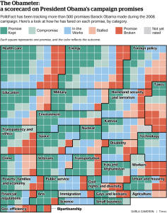
ability to deliver on promises.  Remember that a sitting president, after all is said and done, can only actually do the following: he can make war , veto legislation, and issue Presidential directives (which by definition must not have the same impact as law).

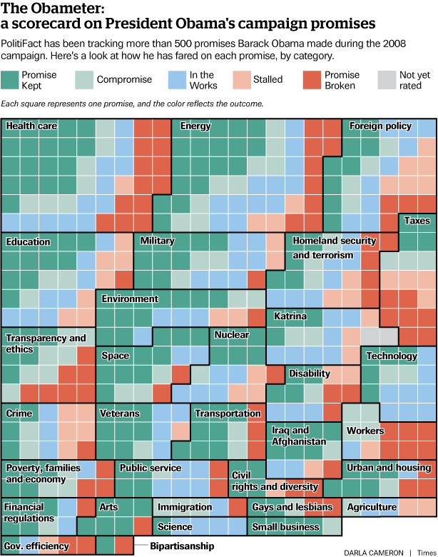
Here then, are the results from two different sources.  First we have PolitiFact.org.  Click on the image to the left for a full size version showing their tracking of more than 500 campaign promises.  What’s nice about this chart is they way they colored everything.  Green is “promise kept”, light green is “compromise”, light blue is “in the works”, light red is “stalled” and red is “promise broken” Assimilation  of the compiled results then becomes a bit more of a visual exercise.  How does it look to you?

Next, we have Al Jazeera’s take on some of the major campaign promises that Obama made in 2008, how he has done on them, and what the contributing issues were that  surrounded their status.  This is an good read from an outside source that in my opinion paints an interesting picture of how the rest of the world might just be viewing our President’s promise legacy.

Source: Al Jazeera
Publication date: October 1, 2012

By the Al Jazeera staff

Economy

Repeal Bush-era tax cuts for high-income earners

During the 2008 campaign, a cornerstone of Obama’s proposed economic plan was to allow tax cuts for those who earn more than $250,000 annually, put in place during George W Bush’s presidency, to expire. The increased government revenues would be used to fund expanded government spending programmes for low-income Americans.

At the end of 2010, however, Obama brokered a major compromise on taxes, agreeing to renew the Bush-era cuts for another two years, in return for a one-year reduction in Social Security taxes and an additional year of unemployment benefits for certain workers, both also promises he made during his campaign.

The tax cuts are now due to expire in December 2012, and Obama has made repealing them a campaign issue once more. Whether or not he’ll be any more successful in his second term remains to be seen.

Increased financial regulation as part of a fiscal stimulus package

In 2008, as then President Bush put into place the Troubled Asset Relief Programme (TARP) to rescue several financial institutions – including Citigroup, AIG, Bank of America and others – Obama promised that he would put into place widespread changes to US financial regulation, making all major financial institutions subject to greater government oversight.

In July 2010, President Obama signed the Dodd-Frank Wall Street Reform and Consumer Protection Act, putting into place the most widespread changes to financial regulation in the United States since the 1930s Great Depression. The Act institutes new rules on mortgage eligibility, gives the federal government the authority to regulate derivatives trading, and institutes greater oversight over hedge funds.

It also creates a new Consumer Financial Protection Bureau and restricts banks’ ability to use customers’ funds in investments.
Critics of Dodd-Frank, however, say that with intense pressure from both Republicans and Wall Street to limit government intrusion in financial market practices, the Act has not had the practical impact that it should have. Others argue that it does not go far enough, and institutionalises the idea of government bailouts for firms that are ‘too big to fail’.

Defense and Security Policy

Revamp US military strategy in Afghanistan 

Obama ordered a comprehensive review of the US military strategy in Afghanistan as soon as he entered office. As a result of the review, he ordered an immediate 30,000 troop surge, with a built-in withdrawal beginning in July 2011. Moreover, US troops would move towards a greater training role, helping an expanded Afghan National Army and local police to secure the country on their own. A full US withdrawal date of 2014 was set.

Obama has been largely successful in making this happen, although questions remain about the effectiveness of the new strategy, heavily focused as it is the counter insurgency (COIN) principle used in Iraq. Foreign casualties soared in by 36 per cent in 2010 as military engagement increased, but began to drop again in 2011 and 2012. Major questions remain about security, however, as the Taliban and Haqqani Network have successfully implemented attacks on major US bases and international targets in the intervening period.

Complete withdrawal of US troops from Iraq on schedule

Obama promised to have all combat troops withdrawn from Iraq within about 16 months of taking office. In August 2010, the final US combat brigade left the country, leaving behind about 50,000 soldiers who were engaged primarily in training and security operations. Those troops, too, left the country a few days ahead of the December 2011 deadline set under the final US-Iraq agreement on troop presence. Security in Iraq is now entirely in the hands of the Iraqi government, with all major US wartime bases closed and remaining troops involved only in diplomatic security or limited training missions. Private security contractors, however, do continue to operate in Iraq.

Close detention facility at Guantanamo Bay

As a candidate for the presidency, Obama unequivocally stated that he would close the US military detention facility at Guantanamo Bay in Cuba. Within two days of taking office in January 2009, he promised to close it within a year.

On March 7, 2011, however, he signed an executive order that made a number of changes to policies regarding those detained at the facility that, among other things, resumed the holding of military trials for detainees. The new policies also established a new process of ‘periodic review’ for captives who were being held without charge, on the justification that they remained ‘at war with the United States’, according to the White House.

The order was widely seen as an admission that the White House had failed in its pledge to close the facility.

End the use of torture by US interrogators in the ‘War on Terror’

In the statement made regarding Guantanamo Bay in January 2009, Obama also addressed the issue of the use of torture by US interrogators (or foreign interrogators on the behalf of the United States). The order stated that prisoners would ‘in all circumstances be treated humanely and shall not be subjected to violence to life and person (including murder of all kinds, mutilation, cruel treatment, and torture), nor to outrages upon personal dignity (including humiliating and degrading treatment)’. It also specifically nullified certain interpretations on federal law regarding interrogations issued under former President Bush.

The American Civil Liberties Union (ACLU) and Human Rights Watch both endorse the view that torture is no longer US policy and does not occur in the systematic and officially endorsed manner that it had since 2001.

Obama has received criticism, however, for his administration’s policy of not aggressively investigating allegations of torture committed before he assumed the presidency. In August 2012, the US Justice Department officially closed the only remaining investigations into torture allegations, without charging any suspects.

In other civil liberties related promises, Obama also pledged to introduce greater oversight on several aspects of the Patriot Act under former President Bush, including warrantless wiretaps. Obama has twice reauthorised several provisions of the Act, including those allowing for such surveillance. Some additional oversight has been enacted, but the Act remains, by and large, unchanged since Obama assumed office.

Changing Washington

Ending partisan politics and ushering a new era of across-the-aisle co-operation

A key part of Obama’s campaign was his promise to bring change to the way that politics was practiced in Washington DC, uniting Democrats and Republicans to work for their constituents, rather than getting bogged down in partisan bickering.

In 2011, the US Congress set new records for partisan voting, according to data from the Congressional Quarterly. The House of Representatives, with a Republican majority body since 2010, set a new record for the number of votes where majorities from each party voted against each other. The Senate, where Democrats are in the majority, was not quite as polarised, but the average Senator for Obama’s Democratic party voted along party lines far more than at any time in the last five decades.

Moreover, by September 2012, the current Congress had passed only 61 bills into law, putting it on course (if it maintains its current pace) to be the least productive legislature since 1947.

While it takes two to tango – and Republicans had pledged on retaking the majority in the House to adopt a policy of non-co-operation with Obama – this still rates as a promise Obama failed to fulfill.

Legislative reform involving ethics and lobbying

During his campaign, Obama promised to create a central database that would provide ‘lobbying reports, ethics records and campaign finance filings in a searchable, sortable and downloadable format’. He also promised to enforce tougher rules restricting officials from taking up lobbying positions and vice versa.

Three years in, in March 2012, the White House launched ethics.gov, which provides exactly that, in addition to White House visitor records and FEC filings. The Obama administration did not, however, make its email and phone records public, as Obama had promised to do as part of an effort to provide greater transparency on lobbyists’ access to the White House.

The promise to curtail the so-called ‘revolving door’ between official and lobbyist positions has been described as the cornerstone of Obama’s lobbying reform project, and on this the administration has failed. Obama signed an executive order saying that former lobbyists would not be allowed to work in an official capacity on subjects related to their lobbying work for a period of two years since they gave up those positions. The administration has, however, granted number of waivers and recusals on this front, meaning that the promise has never entirely been kept.

Social/Other Policies

Introduce broad-ranging immigration reform

During his campaign, Obama promised to introduce broad-ranging immigration reform within his first year in office, including (but not limited to) providing undocumented immigrants with a path to citizenship, securing the border and legally punishing employers who hire undocumented workers.

In 2011, Obama introduced the Development, Relief and Education for Alien Minors (DREAM) Act, aimed at allowing a path to citizenship for illegal immigrants who entered the US as minors, as long they had either completed their education there or served in the US military. The Act was voted down by a Republican-majority lower house in 2010.

His administration has made progress by adopting the Deferred Action for Childhood Arrivals (DACA) policy, which adopts some of the same processes as stipulated in the DREAM Act, but the change is far from comprehensive.

During his 2012 campaign, Obama has stressed that the DREAM Act remains a legislative priority.

Introduce a ‘universal’ health care system in the US

As a candidate, Obama promised that he would sign a ‘universal’ health care bill into law by the end of his first term as president. His complex proposal for wide-ranging health care reform promised to cut health care costs for families, while ensuring that no US citizens were left outside of health care insurance coverage (unless they did so by choice).

In March 2010, Obama signed the Patient Protection and Affordable Care Act (often dubbed ‘Obamacare’ by its critics). The act does indeed ensure that all citizens have health care coverage through insurance providers – either by paying their own premiums, or through government programmes for those who are not able to afford premiums. It also ensures the insurance companies can no longer refuse to cover those with pre-existing medical conditions.

Obama also promised, however, to cut the premiums of a typical US family by up to $2,500 annually as part of his health care reform. While the full economic effect of the law is difficult to gauge, since the act is a complex piece of legislation that allows for those below the poverty line to receive government support in paying premiums, while increasing the bills of others, analysts say that it is unlikely that the ‘typical’ family’s premiums will fall by as much as $2,500 – indeed, many say that costs will rise for those who can afford them.

The Act also reforms Medicare, a government programme that provides health care insurance support for seniors, as per Obama’s campaign promises regarding existing holes in coverage and flaws in accessibility.

Repeal military’s Don’t Ask Don’t Tell policy on homosexual members

As a candidate, President Obama pledged to repeal the US military’s official policy on the sexual orientation of its members. The existing policy stated that gays and lesbians were free to serve in the military as long as they did not openly declare their sexual orientation, and allowed for them to be removed from service if they did so.

In December 2010, Obama signed a bill into law repealing the policy, and, after a nine-month transition and implementation period, ‘Don’t Ask, Don’t Tell’ officially expired on September 20, 2011.

Support the repeal of the Defence of Marriage Act

In 2008, Obama pledged to repeal the Defence of Marriage Act, which states that marriage in the United States can only legally occur between a man and a woman. He said he would replace the 1996 legislation with a law that would provide equal rights to same-sex couples.

As president, while he has taken steps to replace it – the Justice Department said in 2011 that it would stop defending the law in court as it considered it unconstitutional – any further progress on repealing the law or replacing it has stalled.

In May 2012, Obama stated in an interview that he supported the right of gay and lesbian couples to wed. At present, a new bill on the subject, supported publically by Obama, is present before the Senate, but there has been no debate on it in almost a year.

Reduce US domestic oil consumption by 35 per cent by 2030

Obama pledged to reduce oil consumption in the United States by 35 per cent by 2030 by having industries and consumers switch to renewable forms of energy.

While it is almost impossible to say if the US will hit Obama’s target 18 years from now, he has started several initiatives aimed at making the 35 per cent cut a reality. In particular, he has put in place a plan to phase out $300 billion in fossil fuel subsidies internationally, increased a mandate that requires gasoline to be blended with other forms of more environmentally friendly carbon fuels, and provided several incentives to the renewable energy industry.

Also on the environment front, Obama pledged to introduce a cap-and-trade bill to reduce air pollution, using the proceeds to fund the creation of five million new ‘green’ jobs. While the bill stalled in Congress, the Obama administration has frequently pushed for investments in the environment sector (the economic stimulus plan, for example, provides more than $90 billion in grants, tax cuts and other incentives to firms in the sector).
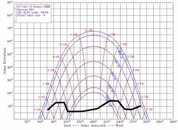
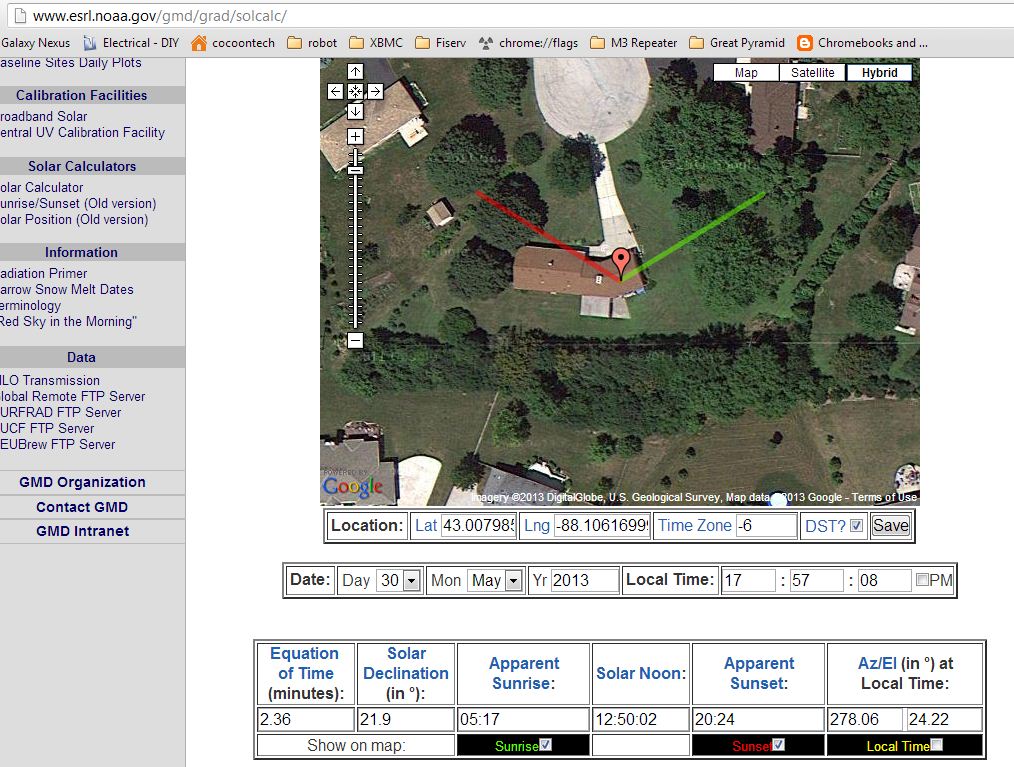
Posted in Politics | Comments Off