
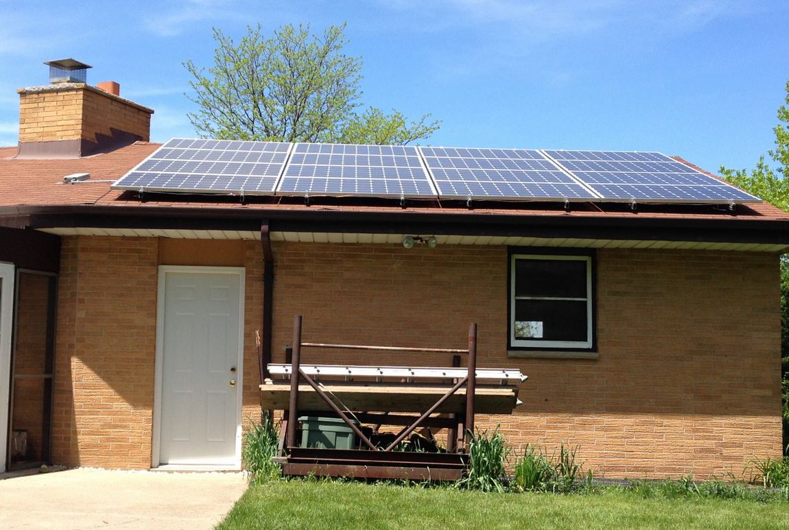
The 3 KW expansion required the addition of 6 more Renusol racks. Each pair secured four 265W Suniva panels. The rails themselves were fastened to the roof using EcoFasten GF flashing at 4 points. Every other rail landed on an existing rafter. As with the 1KW project, I used 4X4s between rafters for the others. When all was finished, the south facing garage roof was completely covered with modules!
So how to do this….
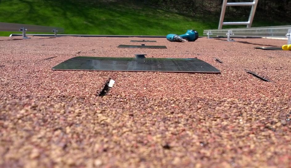
For the rafter mounted rails I followed this process: First, I measured the distance between the topmost rack mount point and the mount point two positions below it on an existing rail from the 1KW installation. Then, underneath the roof and next to the rafter that would hold the new rail, I measured down from the rafter peak board for the first mount point (again using the measurements from an existing rail as my guide). At that spot, I drilled a small 1/8″ hole up through the roof right next to the rafter itself. From that hole, I marked off the distance between mounting point one and mounting point three (determined above) and drilled another 1/8″ hole. I then shoved up two 1/8″ rods so I could easily see where I drilled on top of the roof. Once up there, it was a simple process to position two Ecofasten flashings directly over the rafter at mount point one and three. The 1/8″ alignment holes were no problem because the flashing would cover them completely. Once in place, I sighted down from the top of the roof to perfectly line up flashing two and four with flashing one and three. The following shot shows three of the four flashing assemblies positioned in this manner:
With everything lined up, I drilled 1/4″ pilot holes into the rafter, cut and fit the flashing assemblies into the roofing shingles, installed rail brackets and secured with SPAX lag bolts. The process for the non-rafter aligned rails was identical. However, once the 1/4″ pilot holes were drilled through the roofing deck, I went underneath the roof again and installed 4X4 cross braces wherever daylight showed through… On the bottom of the non-rafter rails, I cheated and left off the almost impossible to install cross brace, instead using a through bolt and large backing washer.
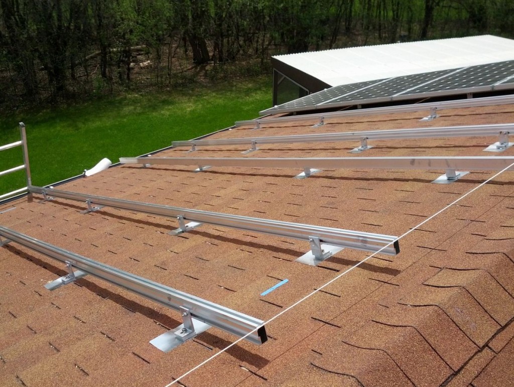
In two days, I had everything mounted. From a sequence perspective, I installed the rack closest to the edge of the roof first. This allowed me to stretch alignment string between the top and bottom so that I could build out a flat array on an undulating roof surface.
 In the photo below you can see a piece of blue tape with a mark on it. This was used to identify the edge of a panel plus a 3/4″ inter panel gap. I simply marked off the dimension on a 2×4 and used it for a gauge.
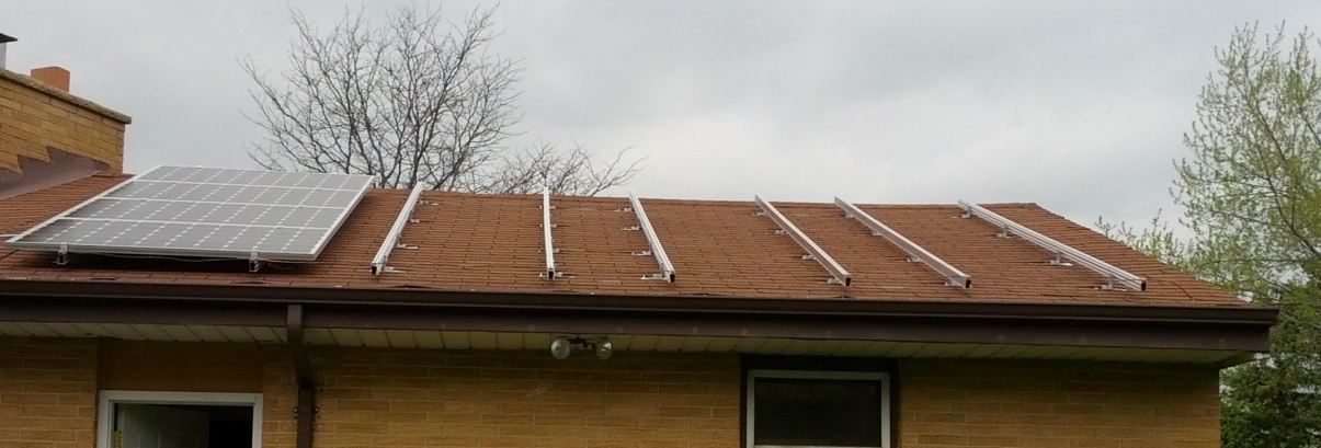
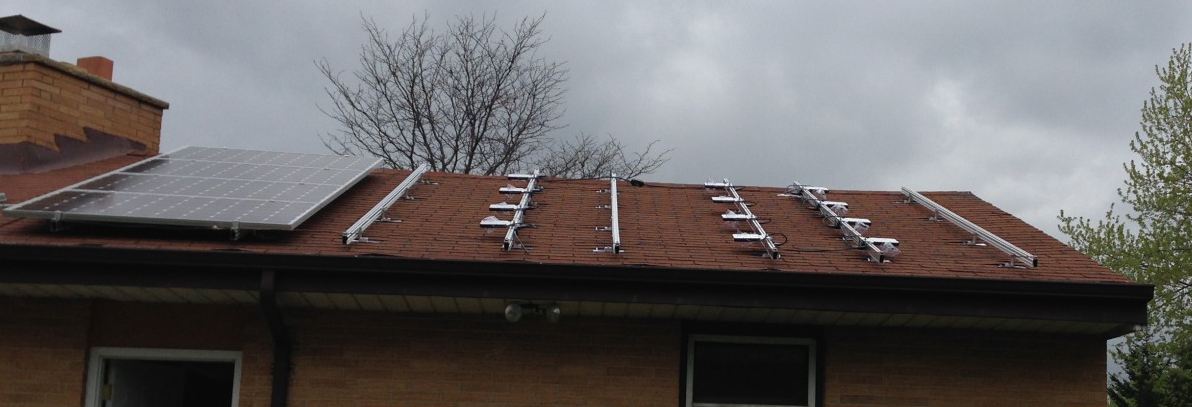
Here’s a shot of the installed racks:
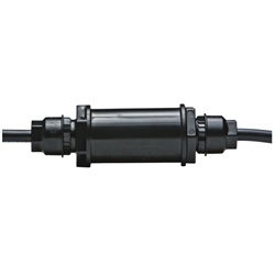
Next, I installed the inverters/trunk cables. The plan here was to extend the terminated trunk cable at the top of the 1KW array using Enphase Engage Couplers (part #ET-SPLK-1 shown below) and 4 conductor TC/ER cable.
 Once extended to the second to leftmost new rail, Engage trunk cable would resume and run up, then across to right side of the second set of racks, then down and across to the left side of the third set. Using this strategy, only one unused connector would be needed.
It was a simple matter to mount the inverters. Here’s what it looked like when I finished (just before a major downpour too). You can see the unused connector at the top of the racks:
Then, we mounted the panels and called New Berlin for our final inspection! By the end of May, the array was producing 3.5KW!
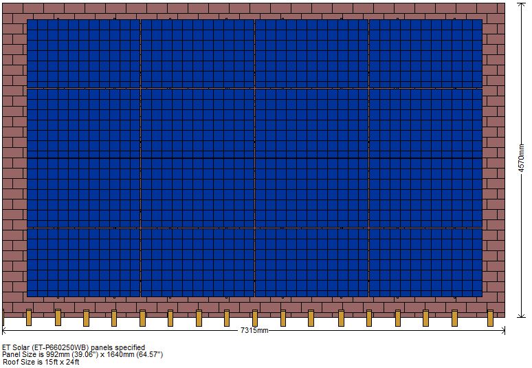
I think its important to make one final point here. What made installing our 4KW array simple and quick was my initial rafter survey. As with any project, careful planning and design work is essential, and this project was no exception. To determine my optimum rail and panel layout, I first went up into the garage and precisely measured the distance between all rafters along with the exact size of the roof itself in millimeters. Using this and panel dimensions from the Suniva cut sheets, I created a precise roof layout using my drafting tool of choice, Home Plan Pro. Once everything was entered, I was able to play around with panel mounts until I had an optimum layout. I wouldn’t want to even think about an installation such as ours without doing this essential, up-front survey work.
Remember to plan carefully before you jump into your own DIY Solar project! Doing a rafter survey is a great winter project that costs nothing at all! Here’s a final shot of the all important diagram that drove this effort:
So what was the bottom line? Stay tuned for my next post!